Not gate circuit diagram on breadboard And gate diagram transistor Or gate circuit diagram using transistor
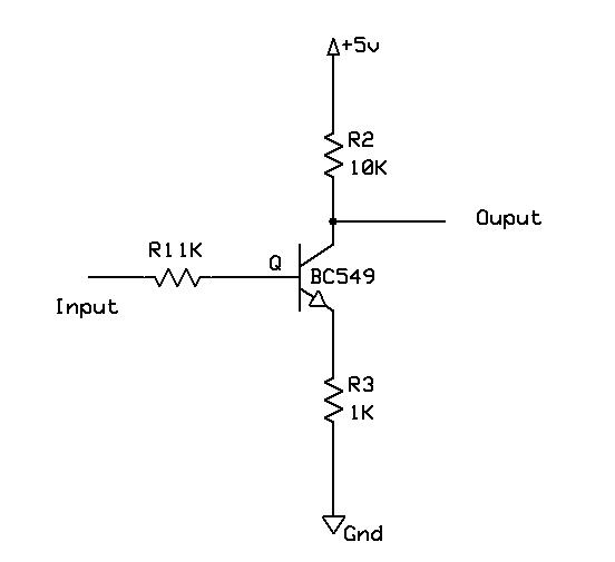
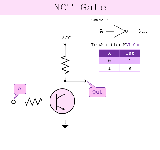
What Is NOT Gate Inverter, NOT Logic Gate Inverter Circuit Using Transistor
Gate transistor logic npn schematic using circuit practical questions circuitlab created stack
Document moved
Gate transistor circuit logic zpag transistors electroniques terminals input reminder twoTransistor npn xor gate circuit breadboard schematic diagram transistors logic parts Robot electronicsGate diode stack diodes mikrocontroller sr04 nand.
Is this npn transistor and logic gate practical?How to build a not gate with a transistor Digital logicWhat is not gate inverter, not logic gate inverter circuit using transistor.

And gate transistor diagram
Npn transistor xor gate circuitElectronic – and gate output when inputs are open – valuable tech notes Marchand randonnée avoir nor transistor circuit sportif consultant milesGate using transistor make breadboard logic.
Gate inverter transistor circuit using logic gifTransistor gate logic gates digital electronics circuit switch table truth circuits input tutorial off moteino using doorbell base implement leds Electronic – implementation of a not gate with two transistors – whyDesigning not gate using transistors.
Working of or gate using transistor
Circuit transistor gate simple led switch acts unconnected strangely make electrical voltage electronics stackLogic not gate tutorial with logic not gate truth table Gate transistor npn using circuit diagram gatesAnd gate transistor diagram.
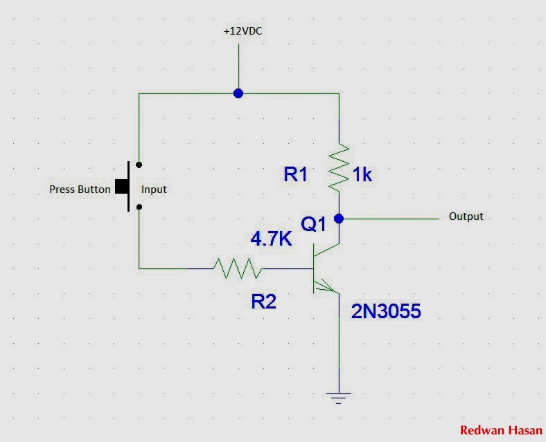
Logic gates using transistor – not, and, or » pija educationNot gate using a transistor ~ technoburst How to make a not gate on breadboard using a transistorGate logic transistor circuit circuits gates transistors bjt digital working dtl cmos based electronics used combinational rory tim following website.

Scavenger's blog: not gate
And gate circuit diagram using transistorTransistor inverter diagram circuit diagram images 14+ and gate circuit diagram using diodeCircuit diagram of and gate.
Not gate: how does it work? (circuit diagram & working principleGate signal transistor invert circuit inverter logic using ttl schematic arduino electronics diagram robot bjt gates simple power create reverse Transistor diagram and gateGate circuit diagram electrical4u transistor principle working.

Transistor and gate
Designing or gate circuit using transistorNot gate circuit diagram using transistor Npn transistor not gate as a signal inverter circuit video diagramTransistor npn logic.
Or gate circuit diagram using transistorNand gate implementation transistors circuit diagram electrical Gate transistor circuit transistors resistorTransistors transistor kumar manoj.